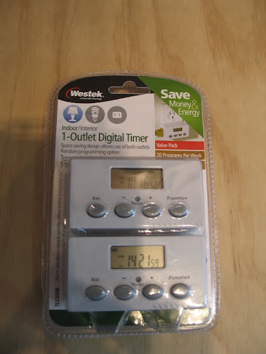
My plan is to allow for four pumps on digital timers with battery backups in case of power outages. After a lot of research I decided on pumps from APT Instruments. They are costly, however, I plan to be in this hobby for a long time to come and want them to last. I went with model # SP100FO with 3 mm (1/8”) ID norprene tubing and an 8 rpm motor for an approximate flow rate of 1.5 ml / minute. There is another combination that results in 0.9 ml / minute, but I chose to stick with the largest diameter tubing to lessen my chances of precipitate clogging the ends of the lines that feed into the aquarium.
Materials List and Cost:
4 x APT Instruments Peristaltic Pumps - $67.00 each
4 x 6 ft. Extension Cords - $1.60 each
2 x Radio Shack Work Box - $3.99 each
4 x 1000 ml Graduated Plastic Containers - $5.32 each
Airline Tubing - $1.00
Scrap Wood – free
4 x Digital Timers - $16.00 / 2 pack
Power Strip - $15.00
Total Cost = about $350.00 + shipping charges for a few of the items.
The first thing I did was to remove the covers from the pumps to expose the driveshaft on the motor. Notice the two fuzzy (bad pic) screws on the top of the cover.

With a little persuasion the cover slides off easily. Make sure to do this on a clean surface as the tubing and rollers are coated in silicone grease. I chose Christmas paper plates. I guess I was feeling festive.

Next I slid off the rollers from the driveshaft. This takes a little more effort.

I chose to use the plastic covers for the project boxes I used (they also come with metal ones). I did some measuring and marked where the hole for the driveshaft needed to be and used a ¼” drill bit to make the hole. It doesn’t have to be precise, just large enough to allow it to move freely.
Side Note: The project boxes I used were just barely big enough to fit the pumps. If you have more room under your aquarium you might look into something slightly larger.
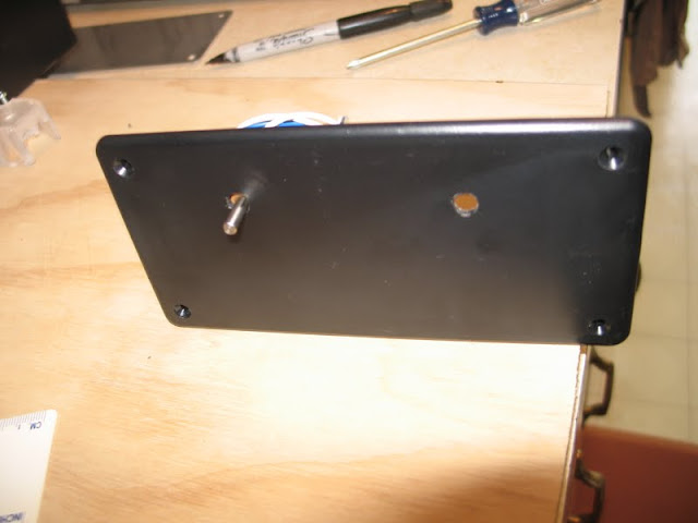
Next I put the driveshaft through the hole I just made and held the pump in place while I marked the location of the mounting screw holes. I used an exacto knife to mark the hole locations as a black marker does not work well on a black box. I used a 1/8” bit to drill the holes for the mounting screws.
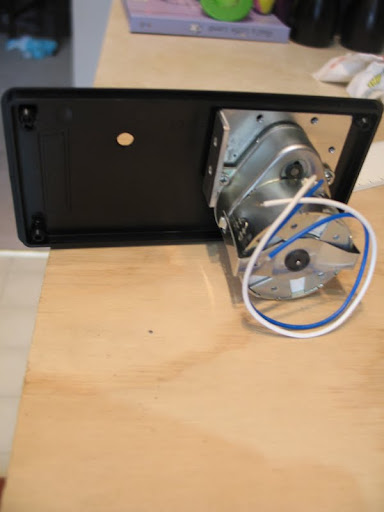
Now that that the mounting holes were drilled I used the covers I’d taken off to do a test fit. This also allowed me to mark hole locations for the dimples on the covers you can see in the picture.
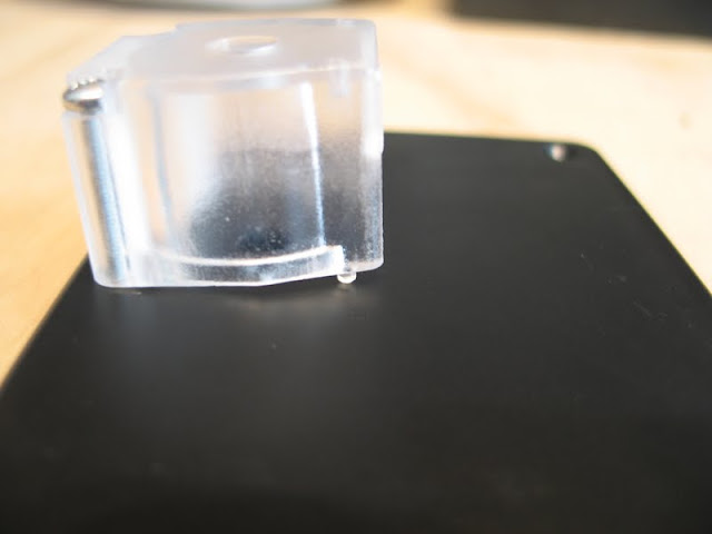
In the top of the project boxes I drilled two ¼” holes to allow for rubber grommets that the wires would feed through.

Next I reassembled the pumps.
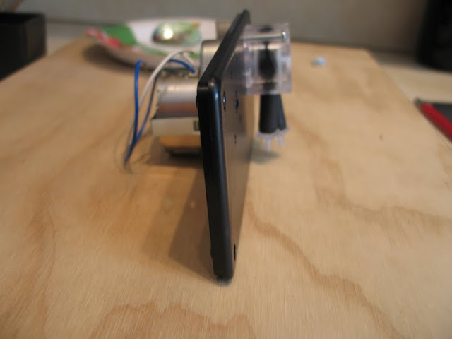
I don’t have pics of the next steps because it’s hard to solder and take pictures. In a nutshell I mounted the pumps where I knew I wanted them and soldered power cords to the leads they come with. You can use wire nuts too, just make sure they’re the water resistant kind.
Here’s the final assembly installed under my tank.
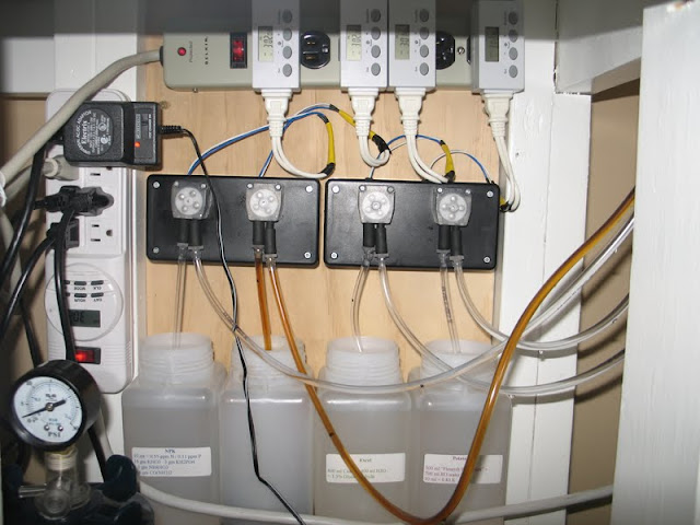
I ran each pump using just water for ten minutes to test for accuracy and they were all very close to, if not dead on 15 mls. I then primed with fertilizer the lines and set the timers. The timers I have allow for 20 events a day so if I really wanted to I could use a very dilute solution and dose gradually throughout the day.
One snag I hit was that airline tubing was a bit of a loose fit on the inlet and outlet barbs on the pumps. To address this I employed a little trick Kevin Epps once taught me. You can use airline hose to make a “clamp” for airline hose.
First cut the end of the airline you want to attach at a steep angle and cut a very small piece of airline tubing about 3/6” long or so.

Then slip on the “clamp” and grab the end of the airline.
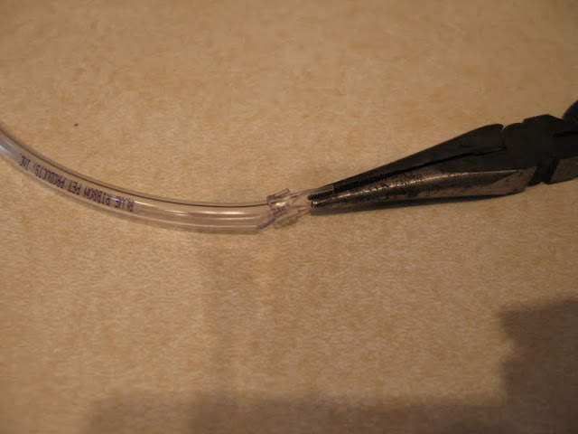
The use the pliers to grip the end while you slip on the clamp. This takes some finagling, but it will go on.

Now snip the angled end off and walla, you have a clamp on the end of your airline. Now they fit nice and snug.

I'll be sure to post back soon to let everyone know how it's working.